Production QC quality inspection
Stator Winding Electrical Performance Parameters Inspection Report
1. Inspection Purpose
During the stator winding process, stator electrical performance parameters (resistance and inductance) are tested to ensure they meet the design requirements. Precise testing using an RC digital bridge ensures stable motor operation, prevents electromagnetic vibration caused by parameter anomalies, and improves product quality and performance.
2. Inspection Equipment
A calibrated RC digital bridge with high-precision measurement capabilities is used to accurately obtain stator resistance and inductance parameters to meet inspection requirements.
3. Inspection Process
● Preparation: Connect the wound stator to the RC digital bridge test terminals according to specifications, ensuring secure connections and good contact. Check the test environment (such as temperature and humidity) to prevent environmental factors from interfering with the measurement results.
● Parameter Testing: Operate the RC digital bridge, select the corresponding test mode (resistance or inductance measurement), start the test program, and read and record the stator resistance and inductance values.
● Comparison and Verification: Compare the test parameters with the standard resistance and inductance values specified in the design drawings to determine whether they are within the allowable tolerance range.
4. Test Results
Stator Hi-Pot Test Report
1. Test Purpose
A hi-pot test is conducted during stator production. An 1800V voltage (300V above the standard) is applied using a hipot tester. The test duration is controlled to 5 seconds, the current is ≤5mA, and no arcing occurs. This verifies the stator insulation performance, ensures leakage-free motor operation, and enhances product safety and reliability.
2. Test Equipment
A calibrated hipot tester is used, which accurately outputs the set voltage, monitors the current in real time, and features arc detection, meeting the high-precision and high-reliability requirements of stator hipot testing.
3. Test Procedure
● Preparation: Connect the stator to the hipot tester electrodes as specified, ensuring secure connections and good contact. Clean the test area, keep it dry, free of conductive debris, and avoid environmental interference.
● Parameter Settings: Set the hipot tester to a test voltage of 1800V, a test duration of 5 seconds, and a current threshold of 5mA. Enable the arc detection function. After confirming that the parameters are correct, start the test.
● Test Execution: The tester automatically increases the voltage to 1800V and maintains it for 5 seconds, while simultaneously monitoring current and arcing. During the test, the voltage output remained stable at 1800V, the current did not exceed 5mA, and no arcing occurred (specific current data was recorded based on actual conditions).
● Result Verification: If no voltage breakdown, current exceeding the limit, or arcing occurred during the entire test, the test is considered passed; otherwise, it is considered failed.
Whole Device Ground Resistance Test Report
1. Test Purpose
This test is conducted on the entire device. By applying a 25A current, the ground resistance value is checked to see if it is less than 90 milliohms. This ensures the reliability of the entire device's grounding system, prevents leakage risks, and improves product electrical safety.
2. Test Equipment
The RK2678XM ground resistance tester is used. It features precise current output and resistance measurement capabilities. It can stably output a 25A test current and accurately obtain ground resistance values, meeting testing requirements.
3. Test Procedure
● Preparation: Connect the whole device's ground terminal to the tester's corresponding interface, ensuring a secure connection and good contact. Check the test environment to ensure there are no interference factors.
● Parameter Settings: On the RK2678XM tester, set the test current to 25A and the timer to 3.0s (as indicated by the instrument), and start the test.
● Test Execution: The tester automatically outputs 25A current for 3 seconds, simultaneously measures and displays the ground resistance value, and records the test data (actual test resistance value must be supplemented according to the result).
● Result Determination: Compare the test resistance value with the standard (less than 90 milliohms) to determine if the test is acceptable.
Class 1 Appliance Leakage Current Test Report
1. Test Purpose
Leakage current testing is conducted on Class 1 appliances (products that rely on basic insulation and grounding for protection). Based on relevant safety standards (such as GB 4706/IEC 60335 series), professional instruments are used to measure leakage current values to ensure they are within standard limits (typically no more than 0.75mA during normal operation). This ensures product electrical safety and mitigates leakage risks.
2. Test Equipment
A leakage current tester (specific instrument model to be specified) is used. It features precise current measurement and stable voltage output, simulating rated voltage conditions and meeting the requirements for Class 1 appliance leakage current testing.
3. Test Procedure
● Equipment Connection: Connect the Class 1 appliance under test according to the instrument specifications. Ensure that the ground and power terminals are firmly in contact with the corresponding connectors on the tester, and verify that the wiring is correct.
● Parameter Setup: On the tester, set the test voltage to the product's rated voltage (or 1.06 times the rated voltage, depending on the standard) and start the leakage current test.
● Test Execution: The tester automatically applies voltage, simulating the appliance's operating conditions, collecting and displaying leakage current data in real time. The maximum and stable leakage current values are recorded during the test (actual test data will need to be supplemented based on the results. For example, during the test, the leakage current stabilized at 0.3mA, significantly below the standard of 0.75mA).
● Result Determination: Compare the test data with the Class 1 leakage current standard (≤0.75mA for normal operation) to determine compliance.
Motor Speed Test Report
1. Test Purpose
A high-precision LED stroboscope tester, which requires no warm-up, is used to test the motor speed at each gear to ensure it precisely matches the design requirements and that the speed deviation is controlled to no more than 1 rpm. This ensures stable motor performance and supports the overall reliability of the equipment.
3. Test Equipment
A high-precision LED stroboscope tester, which requires no warm-up, quickly and accurately captures motor speed information, clearly presenting the motor's operating status at different gears and meeting the high-precision speed measurement requirements.
3. Test Procedure
● Equipment Preparation: Place the motor stably on the test bench, ensuring no shaking or movement. Turn on the LED stroboscope tester and calibrate the instrument parameters to ensure test accuracy.
● Gear Test: Adjust the motor to each designed gear in sequence. Once the motor is running stably, turn on the LED stroboscope tester and aim it at the motor's rotating components (such as the shaft, impeller, etc.). Using the stroboscope synchronization effect, read and record the speed value for the corresponding gear.
● Data comparison: Compare the actual speed of each gear with the design speed one by one to determine whether the deviation is within the range of no more than 1 revolution.
Rotor Automatic Balancing Test Report
1. Test Purpose
Automatic balancing of the rotor is performed according to the G2.5 standard, controlling the single-sided mass deviation within 350mg. Using professional, high-precision dynamic balancing equipment, this ensures smooth motor operation and improves overall motor performance and stability.
2. Test Equipment
Professional, high-precision dynamic balancing equipment, equipped with precise mass detection and deviation analysis capabilities, efficiently completes rotor dynamic balancing tests, meeting the stringent requirements of the G2.5 standard.
3. Test Process
● Rotor Clamping: The rotor to be tested is firmly clamped to the working position of the dynamic balancing instrument using specialized tooling. Ensure a secure clamp and that the coaxiality meets test requirements to prevent clamping errors from affecting the test results.
● Parameter Setting: In the test instrument, set the single-sided mass control threshold to 350mg according to the G2.5 standard and rotor specifications. Confirm parameters such as the test speed and acquisition frequency, and start the test program.
● Test Operation: The instrument drives the rotor, collecting vibration data and mass distribution information in real time, and automatically analyzes and calculates the single-sided mass deviation. During the test, the instrument screen displays the data curve and status in real time. For example, in this test, the final result displayed "OK," indicating that the mass deviation is within 350mg (specific data may be supplemented as needed).
● Result Verification: If the test shows a single-side mass deviation of ≤350mg, the rotor dynamic balancing test is considered passed. Otherwise, it is considered unsatisfactory and requires rotor correction and retesting.
Incoming material inspection
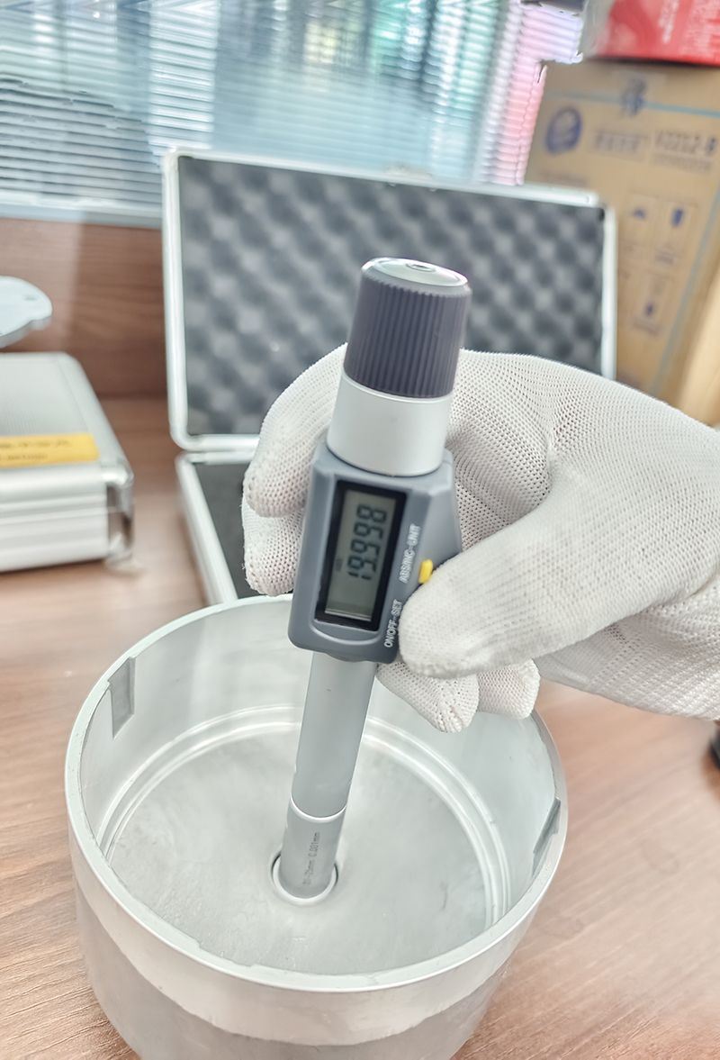
Motor Rotor Dimension Inspection Report
1. Inspection Purpose
Inspect key dimensions of the motor rotor outer ring (such as the shaft hole diameter and the magnet ring mounting diameter) to ensure that each dimension is within a 2-micron tolerance. This minimizes vibration and ensures uniform magnetic field rotational force during rotor rotation.
2. Inspection Equipment
A digital micrometer with high-precision measurement capabilities is used. Calibration is completed before measurement to ensure data accuracy.
3. Inspection Procedure
Wearing protective gloves, remove the motor rotor component to be inspected and place it steadily on the inspection table.
Operate the digital micrometer, aligning it with the shaft hole diameter, magnet ring mounting diameter, and other inspection points. Slowly measure deeply, read, and record the data. For example, the shaft hole diameter displayed in this measurement is 19.998mm (this is sample data; actual complete inspection data must be used).
Repeat measurements at different locations to ensure data consistency and compare the dimensions specified in the drawing with the 2-micron tolerance.
4 Test Results
Testing revealed that all key dimensions of the motor rotor outer ring (such as the shaft hole diameter and the magnetic ring mounting diameter, which are subject to additional verification) were within a 2-micron tolerance, meeting the drawing's dimensional requirements. This ensures minimal rotor vibration and uniform magnetic field rotational force during rotor rotation.
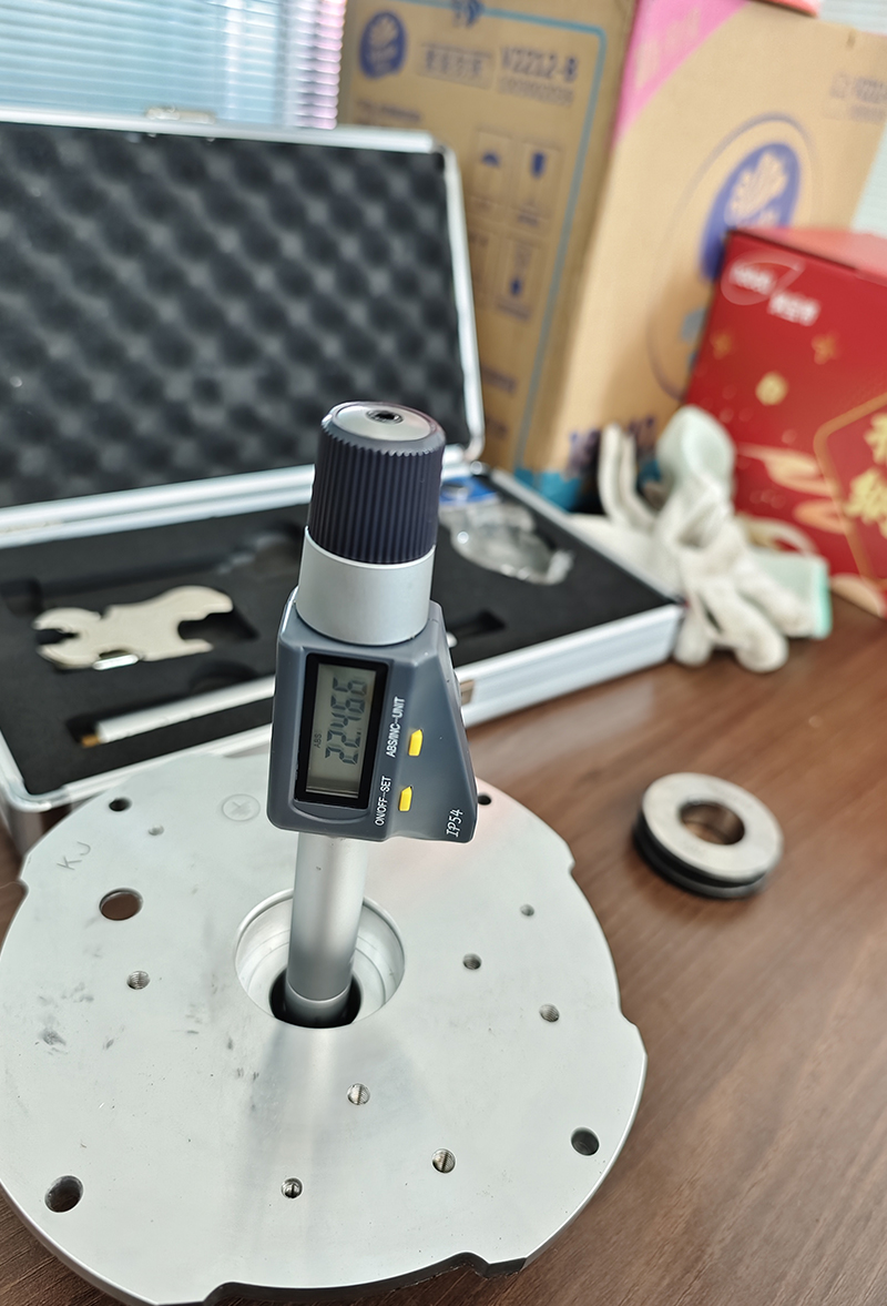
Motor parts (rear housing) incoming material inspection
1. Inspection Purpose
According to the drawing requirements, the motor rear housing is inspected as received. Key dimensions are accurately measured and checked to ensure stability after installation.
2. Inspection Equipment
An internal micrometer (Model: ES-1) is used. This equipment has been calibrated prior to inspection to ensure its measurement accuracy meets the inspection requirements.
3. Inspection Process
Appearance Inspection: A preliminary inspection of the motor rear housing is conducted to confirm that there are no visible surface defects such as cracks, pinholes, or deformation, and that there are no cosmetic issues that would affect subsequent dimensional measurements or motor assembly.
Dimensional Measurement
Place the motor rear housing securely on a clean, flat inspection workbench to prevent movement or shaking during the measurement process.
According to the dimensional requirements indicated on the drawing, an internal micrometer is used to measure key dimensions of the rear housing, including the inner diameter, hole diameter, and slot width. For example, when measuring a specific inner diameter, slowly insert the inside micrometer into the hole and gently rotate it to ensure full contact and proper positioning of the measuring tip. After the reading stabilizes, read and record the data. This time, the inner diameter measurement shows 26.071mm (example data; actual measurements should be recorded in detail based on specific circumstances).
For each critical dimension, perform at least three measurements at different locations to minimize measurement error. After each measurement, carefully record the measurement data.
4. Inspection Results
Dimension Comparison: Compare the measured dimensions with the dimensions specified in the drawing, and calculate the dimensional deviation. After inspection, the deviations for each critical dimension are within the tolerance range of less than 2 mm, meeting the drawing requirements.
Overall Conclusion: Based on the visual inspection and dimensional measurement of the motor rear housing, this batch of incoming motor rear housing materials meets the dimensional accuracy requirements and can ensure the operational stability of the motor after installation. This batch of incoming motor rear housing materials has been deemed qualified.
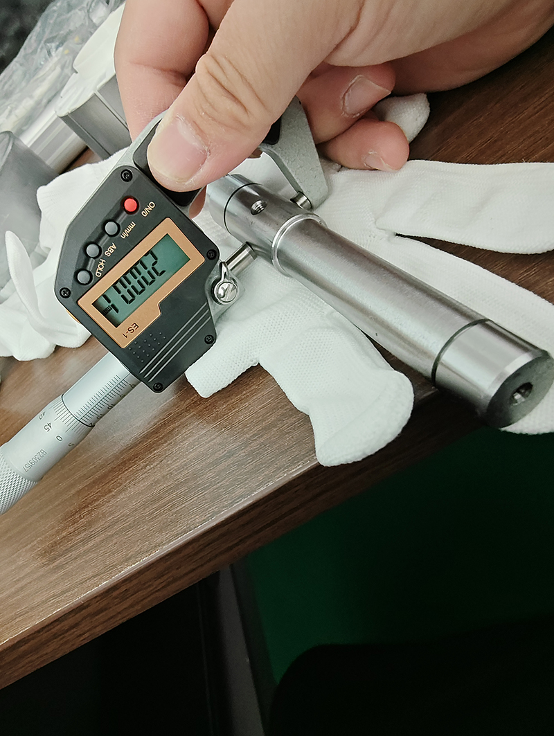
Motor Shaft Incoming Material QC Sampling Inspection Report
1. Inspection Purpose
Incoming motor shafts are sampled for inspection. Key dimensions (bearing position and length) are measured to ensure tolerances meet standards (bearing position ≤ 0.003mm, length ≤ 0.3mm) to ensure stable motor operation. As the motor shaft is a core component, dimensional accuracy significantly impacts performance.
2. Inspection Equipment
Calibrated outside micrometers and calipers are used for precise shaft dimension measurement. The equipment accuracy meets inspection requirements.
3. Inspection Process
Sampling Selection: Randomly select samples from the incoming batch of motor shafts according to [specific sampling rules, such as GB2828] to ensure representativeness.
Dimension Measurement
Bearing Position Dimensions: Use an outside micrometer to gently fit the motor shaft bearing installation location. Measure multiple sections of the motor shaft, record the data, calculate the tolerances, and check for tolerances of ≤ 0.003mm.
Length: Use a caliper to measure the motor shaft length at both ends and in the middle, taking the average of the values and determining if the error is ≤ 0.3mm.
Data Recording and Analysis: Record the measurement data in detail, compare it to the standard error range, and analyze the sample's dimensional compliance.
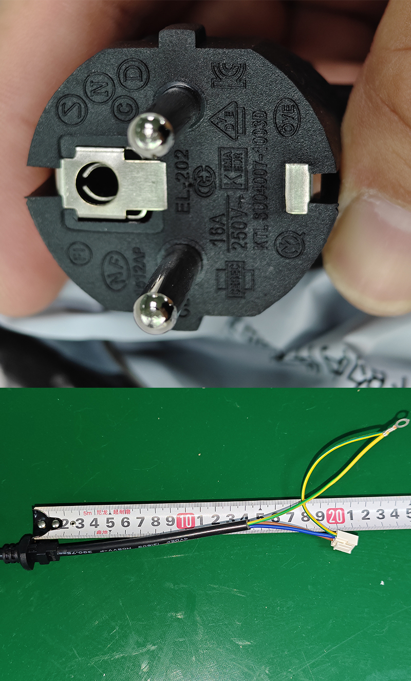
Power Cord Incoming Material Inspection Report
1. Inspection Purpose
Incoming power cords are thoroughly inspected, covering dimensions (cord length, diameter, and sheath thickness) and printed content (cord and plug) to ensure that the model complies with safety regulations and meets the safety certification requirements of the customer's local market, thereby ensuring product compliance and quality.
2. Inspection Equipment
A calibrated ruler and caliper (digital display) are used for precise dimensional measurement. Visual inspection of printed content is aided by a standard light source and safety documentation.
3. Inspection Process
(I) Dimension Measurement
Cord Length: Place a ruler along the power cord axis and measure the effective length of the cord. Record the data and check for consistency with the designed value.
Cord Diameter: Use a caliper to measure the diameter of the cord at different locations. Average the measured values multiple times to determine if the cord meets specification tolerances.
Shell Thickness: Carefully press the caliper against the outer surface of the cord to measure and calculate the thickness to ensure compliance with insulation and safety regulations.
(2) Printing Inspection
Line Printing: Under sufficient light, visually inspect the model number, specifications, and other information printed on the surface of the line to verify compliance with safety regulations. Check the clarity and completeness of the printing.
Plug Printing: Observe the model number, certification markings, and other information printed on the plug surface. Based on safety documentation, confirm compliance with the model and marking specifications specified by the customer's local market safety certification.
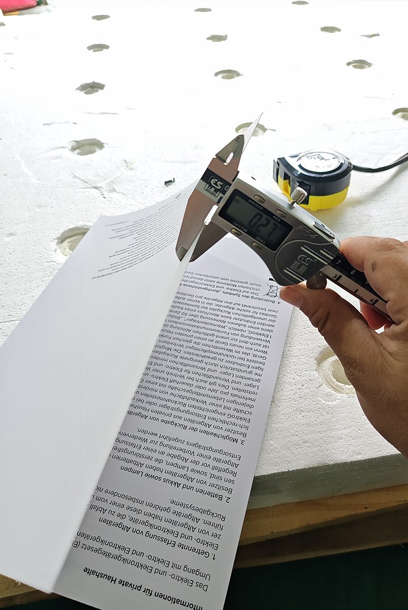
Instruction manual incoming material inspection
Test items and results
(1) Content printing error detection
The contents of the manual were checked page by page and paragraph by paragraph. No spelling errors, sentence logic errors, information omissions and other printing errors were found. The content was accurate and complete.
(2) Content clarity detection
By observing under natural light and auxiliary light sources, the text and patterns of the manual were printed clearly, the ink was evenly distributed, and there were no blurring, ghosting, fading and other problems that affect reading, meeting normal reading requirements.
(3) Material detection
Using [specific material identification methods, such as combustion method, component analysis instrument detection, etc., which need to be combined with actual conditions], the paper material used in the manual was tested to confirm that its material is consistent with the [customer required material name] required by the customer, and the physical properties of the paper such as thickness and toughness meet the standards. The paper thickness was measured with a caliper [specific measurement data, such as this measurement shows 0.27mm, combined with customer requirements to determine whether it meets the standard], which is within the material parameter range required by the customer.
(4) Dimensional Inspection: Use calipers, tape measures, or other tools to measure the dimensions of the instruction manual, including length, width, and thickness. After measurement, compare the dimensions of each side of the instruction manual (specific measurement data) with the customer's required dimensions (customer-required dimensions). If the deviations are within the allowable tolerances, the dimensions are considered acceptable.
Incoming Material Inspection Report for Complete Machine Structural Components
1. Inspection Purpose
Incoming material inspection is conducted on other structural components of the complete machine (such as upper and lower motor connectors, wall fan brackets, etc.). Dimensions are measured according to the drawings, and dimensional errors are controlled (maximum dimensional error ≤ 2.5mm, minimum dimensional error ≤ 1mm) to ensure proper installation of the complete machine and enhance product durability.
2. Inspection Equipment
Use calibrated rulers and calipers (such as digital calipers) to ensure measurement accuracy meets inspection requirements.
3. Inspection Process
Preliminary Appearance Inspection: Inspect the surface of the components to confirm the absence of deformation, cracks, burrs, and other cosmetic defects that could affect assembly and performance.
Dimension Measurement: Based on the drawings, use a ruler and calipers to measure each dimension (at least three times) of the motor connectors, wall fan brackets, and other components multiple times at different locations, recording the data. For example, for the motor connectors, measure the pipe diameter and connection lug dimensions; for the wall fan brackets, measure the frame length and mounting hole spacing.
Error determination: Compare the measured dimensions with the drawing requirements to determine whether the error exceeds the range (largest dimension error ≤ 2.5mm, smallest dimension error ≤ 1mm).
Incoming inspection of wall fan brackets
Inspection of upper and lower motor connectors
Complete machine components (mesh cover inspection)


